Let’s learn how to design Smart Irrigation System using GSM Module and control DC Motors remotely by sending SMS through a smartphone.
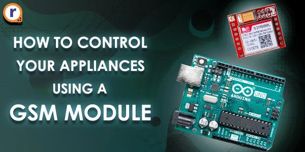
In this article, we will learn how to operate a motor from remote locations using Arduino and GSM Module.
The idea behind this project is powered by the problems faced by the Indian Farmers.
You might have noticed that in most of the cases the crop-fields are located far away from the farmer's residence. Farmers have to travel significant distances to go to their crop fields.
Irrigation is an essential part of farming. As we know, it needs to be done daily, and due to this fact, whatever may be the distance between farm and home, the farmer has to go to their crop fields every day to turn on the irrigation system and supply water to crops.
There are two cons of this daily travel to crop fields, waste of both time and money.
So, we felt like traveling is not a viable option when it can be done remotely. With GSM based agriculture motor control it's that simple; sitting at home, clicking a button on your smartphone and controlling motors!
Note that this project is very easy to do and can be done with minimal hardware and efforts. So whether you're a beginner or an electronics expert, you will be able to do it.
Advantages of GSM Based Agriculture Motor Control
- It will save farmers time and money
- Farmers can control land moisture from a remote location
- Increases productivity
- Farmers can invest time in other vital tasks
- It is very easy to design and implement
Stick with us, and let's dive into the actual project,
Working of Smart Irrigation System
We have tried to simplify this system/project as much as possible to make it easy for everyone, from beginners to experts.
Let me explain the overview of working of this smart irrigation system,
The GMS module is connected to Arduino. When the farmer shoots a message to turn ON the motor, it will be received by the GSM module. Then GSM module forwards this message as a signal to the Arduino board.
After this, the Arduino will make the relay input HIGH, resulting in turning ON the motor pump and this way our smart irrigation system will start supplying the water to crops.
The procedure remains same while turning OFF the motor. This time the farmer will send a message to turn OFF the motor, and the relay output will be made LOW which is then followed by the shutdown of the water pump.
For in-depth understanding of the working refer to the following Flow-Chart,

What is GSM Module?
The main purpose of our smartphone/cellular phone is to receive and make calls and send SMS, this task is achieved by GSM/GPRS module integrated into the device.
GSM module is a specialized type of modem which accepts a SIM card, and operates over a subscription to a mobile operator, just like a mobile phone.
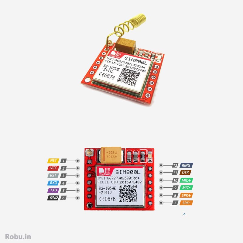
It can be handled with multiple AT commands to perform various tasks. I have attached the datasheet that includes the AT command with the necessary description, please check the given PDF.
Components used in this Project
For making such a well efficient system you will need the following components,
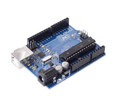 | 1 x Arduino UNO | Add to Cart |
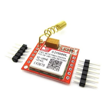 | 1 x GSM Module | Add to Cart |
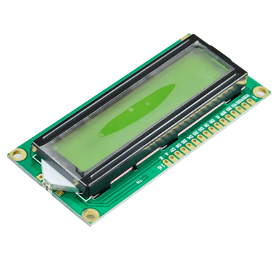 | 1 x LCD Board | Add to Cart |
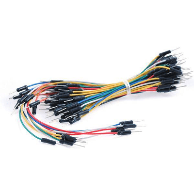 | 1 x Jumper Wire | Add to Cart |
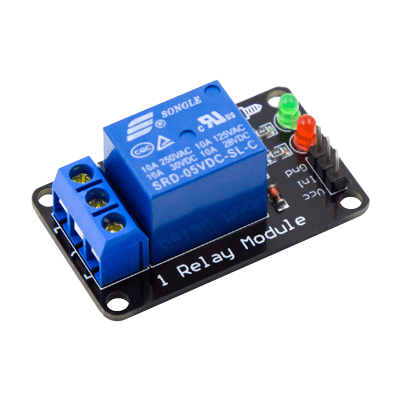 | 1 x 5V DC Relay | Add to Cart |
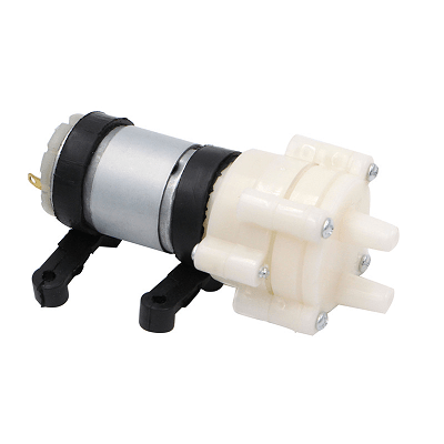 | 1 x Water Pump | Add to Cart |
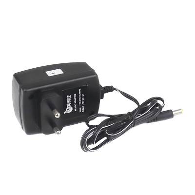 | 1 x Power Supply | Add to Cart |
All of the products required for this project are available at Robu.in.
If you consider buying them from a different website then check if the specification matches or not.
Connection Diagram
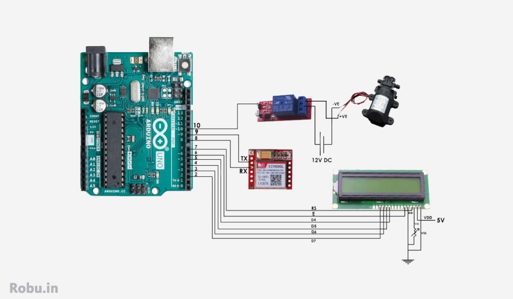
Connecting LCD Module
Refer to the following table to connect the Arduino with the LCD module.
| Arduino Pin | LCD |
|---|---|
| Pin 7 | RS |
| Pin 6 | EN |
| Pin 5 | D4 |
| Pin 4 | D5 |
| Pin 3 | D6 |
| Pin 2 | D7 |
Connecting GSM Module
I hope you have carefully studied the pinout of the GSM module given at the start of this blog.
Connect the Vcc of the GSM module to the 5V supply on the Arduino board. Next, connect the ground of the GSM module to the ground pin of Arduino.
Further,
- Rx of GSM – Tx of the Arduino (Pin 8)
- Tx of GSM – Rx of the Arduino (Pin 9)
That's it for the GSM module.
Connecting Motor (Water Pump)
The Arduino is connected to the water pump through the relay.
So before proceeding further, we need to connect the relay board to Arduino. Hence, connect the relay pin to pin-10 of the Arduino board.
Next, the relay is connected to the water pump and a power supply.
Connect the relay NO pin to the one terminal of the water pump. Another terminal of the water pump should be connected to the +ve of 12V power supply.
At last, connect the common pin of the relay to the –ve of 12V power supply.
Code
con st int motor = 10;

#include <LiquidCrystal.h>
const int rs = 7, en = 6, d4 = 5, d5 = 4, d6 = 3, d7 = 2;
LiquidCrystal lcd(rs, en, d4, d5, d6, d7);

#include <SoftwareSerial.h>
SoftwareSerial SIM900(9,8);
String textMessage;
String message, motorState;


 void setup() {
  pinMode(motor ,OUTPUT);

  Serial.begin(19200);
  lcd.begin(16, 2);
  lcd.setCursor(0, 0);
  lcd.print("system is on");
  delay(1500);

  SIM900.begin(19200);
  delay(3000);
 Serial.print("SIM900 is ready to send receive sms");
  SIM900.print("AT+CMGF=1\r");     // AT command to set SIM900 to SMS mode
  delay(100);
  SIM900.print("AT+CNMI=2,2,0,0,0\r");       // Set module to send SMS data to serial out upon receipt
  delay(100);

   SIM900.println("AT+CMGF=1"); // Replace x with mobile number
  delay(1000);
  SIM900.println("AT+CMGS= \"+9183*******7\"\r"); // Replace * with mobile number
  delay(1000);
  SIM900.println("System is On");// The SMS text you want to send
  delay(100);
  SIM900.println((char)26);// ASCII code of CTRL+Z
  lcd.clear();
}

void loop() {

   if(SIM900.available()>0){
   textMessage = SIM900.readString();
   Serial.print(textMessage);
   delay(10);
   }
   if(textMessage.indexOf("motor on")>=0){
    lcd.clear();
   digitalWrite(motor, HIGH);
    motorState = "on";
    Serial.println("motor set to ON");
    textMessage = "ON";
    lcd.setCursor(0, 1 );
    lcd.print("motor on");
    delay(1000);
  }
  if(textMessage.indexOf("motor off")>=0){
    // Turn off relay and save current state
    digitalWrite(motor, LOW);
    motorState = "off";
    Serial.println("motor set to OFF");
    textMessage = "OFF";
  }
    if(textMessage.indexOf("state motor")>=0){
    String message = "motor1 is " + motorState;
    sendSMS(message);
    Serial.println("motor1 state resquest");
    textMessage = "";
  }
In this code, we have added #include <SoftwareSerial.h> library for adding additional serial port for GSM module,
Rx of Arduino——– Tx of GSM
Tx of Arduino——–Rx of GSM
String ” textMessage” is used to store the string data which gets received from a GSM module. We have added a condition if a string data is get matched with the string data we have added in “if” condition then motor get turned on. For eg., if the GSM module receives a string data “motor on” then the condition is get satisfied and the motor/ water pump will get tur on, Similarly for text “motor off” motor/ water pump will get turn off.
How to Use Smart Irrigation System
Precautions
- While compiling this code, please replace symbol * with your mobile number. Otherwise, you won't be able to get a status message.
Here is a sample status SMS,
SIM900.printIn(“AT+CMGS=\”+919876543210\”\r”); // - To know the motor's current status, you need to send the SMS as "State Motor".
- Make sure that the Incoming and Outgoing service is enabled on the inserted SIM card. If not, then contact your service provider or recharge the SIM card.
- Keep this whole setup packed in a dry place.
Here Are the Steps to Use Smart Irrigation System
Step 1 – Turn on the System. This will trigger an acknowledgement message to your number.
Step 2 – Send SMS "Motor On" to the number **********.
Step 3 – It will be received by GSM and sent to Arduino.
Step 4 – Arduino will turn ON the water pump through the relay.
Step 5 – The irrigation will start.
Step 6 – Now, after a perticualar time, send SMS "Motor Off" to the number **********.
Step 7 – Here the Step-3 will be repeated, and the process in step-4 will be reversed, and the motor will be turned OFF.
Intermediate Conditions
If you wish to check the status of the motor then you can just send an SMS as "State Motor" to the number **********.
Final Words
Thank you for being with us till the end. I hope you are looking forward to doing this project on your own. If you have any doubts, then don't forget to comment below. I would like to help you.
As you might have seen that this project requires very few components and is easy to use. No extra application or software needs to be installed, so it is very convenient for beginners and farmers.
If you want to learn the GSM module and control things remotely, this is one of the best and easy projects available.
This is a very small project that can solve a big issue in a farmer's life by saving their time and money.


