The IOIO-OTG is a board which allows you to quickly and easily interface electronic circuits to an Android device or a PC: Connect the IOIO-OTG to the Android / PC using USB or Bluetooth. Power the IOIO-OTG (not required if operating in USB device mode, see below).
Connect your circuits to any of the 46 I/O pins available on the IOIO-OTG. You can power your circuits off of the IOIO-OTG too. Write a Java program to control the I/O pins, using a high-level API using the provided libraries.
A switch on the board can be used to force the IOIO-OTG into host mode, but most of the time the board can be left in ‘auto’ mode and it will detect its role in the connection. New application firmware is frequently released and can be upgraded without needing a programmer using the IOIODude application. Additionally, this version of the IOIO-OTG has corrected the IC power failure issue due to the onboard switch voltage regulator failing as well as adding a missing decoupling cap on the AVIN pin. This new IOIO-OTG has fixed the problems that plagued the previous version making it a true vision of how the board is intended! You can find out more about these updates
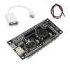
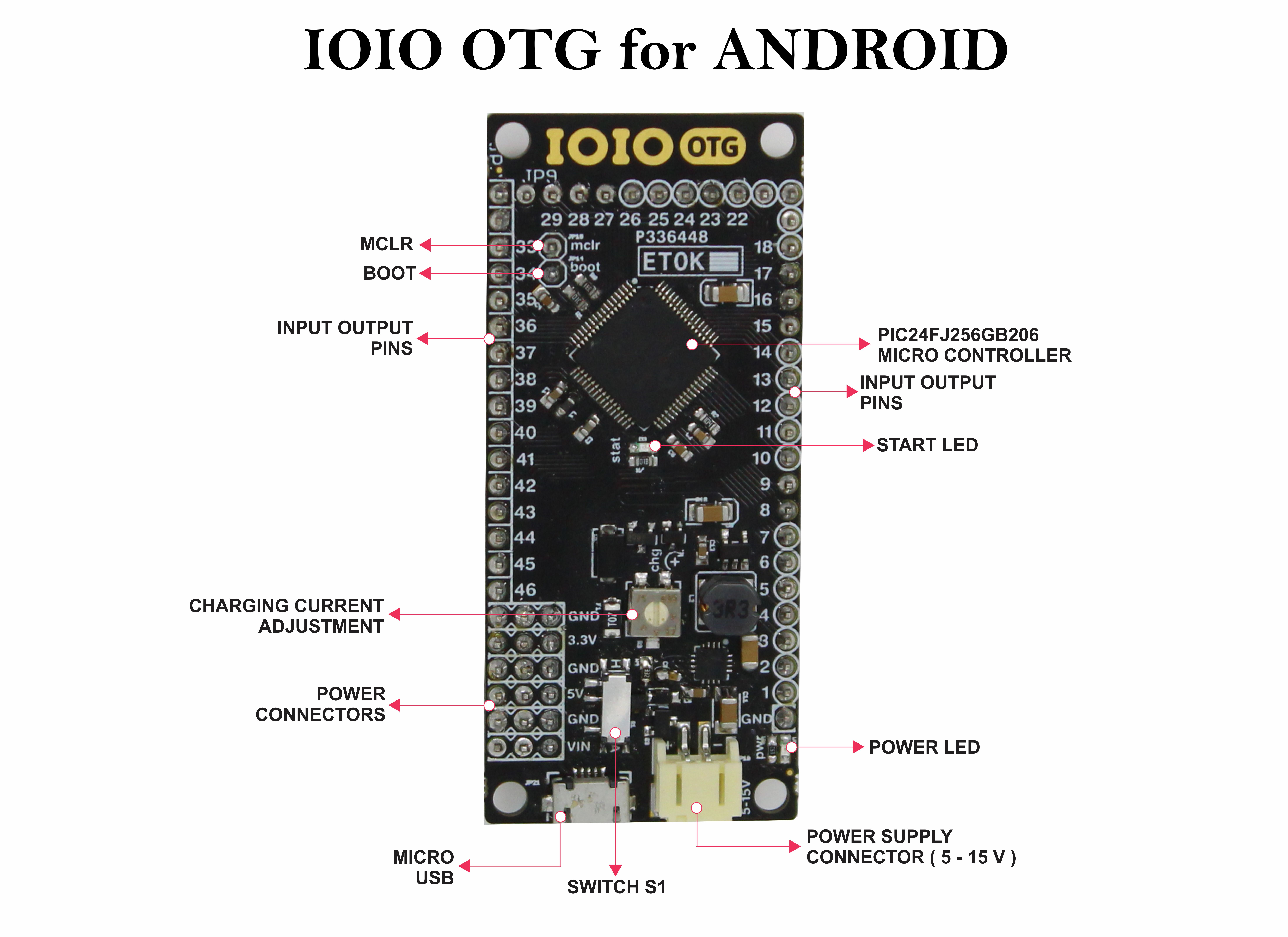
The board includes a JST connector for attaching a LiPo battery and there are several pin headers broken out for voltage and ground access. A trimpot on the board allows you to adjust the charge current used when the IOIO-OTG is acting as a host. A USB-A to micro-A OTG cable is included which will let you connect your android device to the micro-USB port on the board using the cable that came with your Android device.
The kit does not require any soldering and is recommended for people at an intermediate programming level; meaning we hope you have a foundation in writing code and know some basics about electronic hardware. Motivated beginners are welcome, but warned that it may be quite difficult especially if you are unfamiliar with the basics of programming.
TECHNICAL DETAILS
Power Supply
The IOIO-OTG can be powered in one of two ways:
1. By supplying 5V-15V to its JST connector. Do not exceed 10V if using long wires between the power supply and the IOIO-OTG or you might damage the board. The IOIO-OTG has an onboard 5V switching regulator, capable of sourcing up to 500mA continuous. Your power supply has to be capable of sourcing sufficient current for your application. Keep in mind that when connected to an Android device with the IOIO acting as a USB host, the IOIO will charge the Android, which may consume up to 500mA @ 5V. You can limit the charging current somewhat using the trim-pot marked “CHG” on the board.
2. Over USB, whenever the IOIO is acting as a USB device. When working in this mode, make sure that the total current draw of your circuit does not exceed 500mA. Otherwise, it is perfectly OK to connect an external power supply, as described above, in addition to acting as a USB device. In this mode, the IOIO will only draw current from the external supply.
Connecting to Android / PC
- All the following connection modes are supported:
- Connecting to Android, IOIO acting as a USB host. Connect the included USB-OTG cable to the IOIO, then use a standard USB cable to connect the Android device. For working with older Android devices (down to Android V1.5!), make sure to enable USB debugging on the Android. In this mode, the IOIO charges the Android.
- Connecting to Android over Bluetooth. Plug the USB-OTG cable into the IOIO and connect a standard Bluetooth dongle to its other end. Go to the Bluetooth settings on your Android, find the IOIO and pair with it.
- Connecting to Android, IOIO acting as a USB device. This is only supported by newer Android devices, which have the capability to act as a USB host. Connect a USB-OTG cable to the Android device, and a standard USB cable to the IOIO. In this mode, the Android powers the IOIO.
- Connecting to PC, IOIO acting as a USB device. Connect the IOIO to the PC using a standard USB cable. In this mode, the PC powers the IOIO.
Whichever connection mode you use has ZERO impact on the application code that you have to write. In fact, any program you write will automatically support all connection modes and you can even change the connection while the program is running.
I/O Capabilities
The IOIO supports a wide range of commonly used hardware interfaces, all of which can be used concurrently:
46 GPIO pins (digital input / output). Internal pull-ups/pull-downs / open drain mode is supported on all pins. 21 of which are 5V-tolerant.
16 analog inputs (use on designated pins).
9 PWM outputs (use on any pin marked “P”).
3 UART buses (use on any pin marked “P”).
3 I²C buses (use on designated pins).
3 SPI buses (use on any pin marked “P”).
6 pulse input channels for measuring pulse width and frequency – 3 single-precision + 3-double precision (use on any pin marked “P”).
6 capacitive sensing inputs (use on analog pins).
FIRMWARE UPGRADES
New firmware bundles are occasionally published with improvements and new features. The firmware upgrade process is fast as simple and accomplished by connecting the IOIO to a PC and starting it in bootloader mode.
Features:
- 2 Pin 2mm SMD JST Right-angle Connector for Input supply
- On-board TPS62133RGTT Synchronous step down DC-DC converter.
- Power Status LED (RED)
- Micro USB for Communication with Android.
- One start LED connected to boot pin (RC12 =Pin no. 39).
- User Switch SW1, SW2 connected to any port pin through SW1, SW2 Jumper respectively.
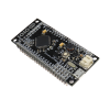
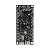
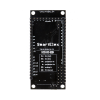
- Port extensions for all ports with detailed pin labeling for easy identification of pins
- Vin, 5V, 3.3V and GND bus provided for external peripheral.
- Four 3mm mounting holes for easy mounting
Package Includes:
1 x IOIO-OTG Development Board
1 x Micro USB-B type OTG Cable
1 x Battery connecting Cable with JST Plug




There are no reviews yet.