Inductive Proximity Sensor Working Principle
This blog focuses on the technology behind the inductive proximity sensors, applications, advantages and disadvantages.

Hello Geeks, Here we will discuss the inductive proximity sensor working principle, their wide spread applications in industries, and their use for commercial purposes. This blog focuses on the technology behind inductive proximity sensors and their detailed specifications.
What is an Inductive Proximity Sensor?
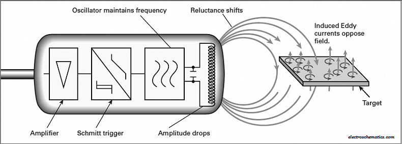
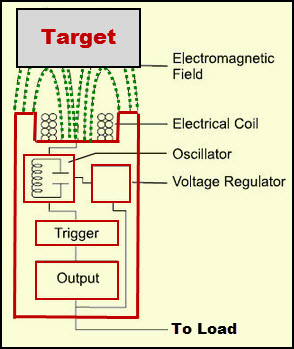
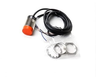 The inductive proximity sensor detects the metallic object that is present next to its active side. This sensor operates under the electrical principle of inductance, where a fluctuating current induces an electromotive force (EMF) in a target object. These non-contact proximity sensors detect ferrous targets, ideally mild steel thicker than one millimetre. They consist of four major components: a ferrite core with coils, an oscillator, a Schmitt trigger, and an output amplifier. This sensor has two main versions and they are:
- Unshielded: Electromagnetic field generated by the coil is unrestricted, allowing for wider and greater sensing distances
- Shielded: The electromagnetic field generated is concentrated in the front, where the sides of the sensor coil are covered up
MUST READ:
Working Principles of Inductive Proximity Sensor
The oscillator creates a symmetrical, oscillating magnetic field that radiates from the ferrite core and coil array at the sensing face. When a ferrous target enters this magnetic field, small, independent electrical currents (eddy currents) are induced on the metal’s surface.
An inductive proximity sensor has a frequency range of 10 to 20 Hz in AC, or 500 Hz to 5 kHz in dc. Because of magnetic field limitations, inductive sensors have a relatively narrow sensing range from fractions of millimetres to 60 mm on average
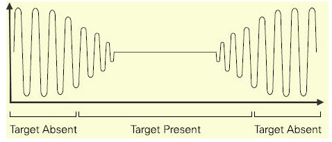
Due to this, load will be caused on the sensor that decreases the electromagnetic field amplitude. If the metal object moves towards the proximity sensor, the eddy current will increase accordingly. Thus, the load on the oscillator will increase, which decreases the field amplitude.
The Schmitt trigger block monitors the amplitude of the oscillator and at a particular level (predetermined level) the trigger circuit switches on or off the sensor. If the metal object or target is moved away from the proximity sensor, then the amplitude of the oscillator will increase.
The above image shows the waveform of the inductive proximity sensor oscillator in the presence of the target and in the absence of the target.
Nowadays, inductive proximity sensors are available with different operating voltages. These inductive proximity sensors are available in AC, DC, and AC/DC modes (universal modes). The operating range of the proximity sensor circuits is from 10V to 320V DC and 20V to 265V AC.
Advantages of Inductive Proximity Sensors
- Contactless detection
- Environment adaptability- resistant to common conditions seen in industrial areas such as dust and dirt
- Capable and versatile in metal sensing
- High switching rate
- No moving parts, ensuring a longer service life
Disadvantages of Inductive Proximity Sensors
- Lack in detection range, averaging a max range of up to 60 mm
- Can only detect metal objects
- External conditions like extreme temperatures, cutting fluids, or chemicals affect the performance of the sensor.
Applications of Inductive Proximity Sensors
- Machine tools, assembly lines, automotive industry
- Detection of metal parts in harsh environments
- High-speed moving parts
Hope this article will help you to understand the complete inductive proximity sensor working principle.
We at Robu.in the hope that you found it interesting and that you will come back for more of our educational blogs.


